
There are a number of mechanical and operational factors to take into account while installing rupture discs in order to decrease the possibility of leaks and fugitive emissions.
Within chemical processing plants and oil refineries, overpressure relief systems made up of rupture discs and relief valves are essential for preventing damage and harm. When installed, maintained, or specified incorrectly, these systems have leakage or fugitive-emission issues. Such leakage problems may have negative effects, such as contamination, corrosion, product loss, and clogging. Other, more severe outcomes could include putting workers and the public in risk, paying fines or cleanup costs imposed by regulatory bodies, and losing output as a result of unscheduled shutdowns.
Less or no leakage occurs through the intended overpressure relief path thanks to rupture discs. However, adequate device sizing and installation are necessary to prevent leaking to the atmosphere between the rupture disc and holder. Additionally, meticulous examination, appropriate cleaning, and routine maintenance of components are required. Users can reduce leakage and fugitive emissions in their plant’s overpressure relief systems by understanding the various rupture disc technologies, assembly types, and sealing mechanisms used.
Use of Rupture Discs for Relief Valve Isolation
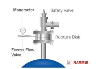
Rupture Disc and Safety Valve in Series
The isolation of pressure relief valves is the most typical application for rupture discs. In order to provide pressure to sealing surfaces and keep the process media contained, pressure relief valves use springs or other mechanisms. When there is an overpressure occurrence, the sealing surfaces are forced to split, releasing process fluids up until the predetermined pressure is reached. The remaining pressure is now contained by the sealing surfaces after the relief valve shut closes. Without rupture discs, at operating pressures close to or above 90% of the set pressures the relief valves start leaking. This case can be serious for applications involving flammable media particularly Hydrogen gas. Hydrogen molecules are very small and more likely to leak as compared to any other gas. Hydrogen is also one of the most explosive gases. It can readily explode after leaking through the safety valve even at lower concentrations and at ambient temperature.
Without rupture discs, relief valves frequently leak, especially if operating pressures are too close to the relief valve’s fixed pressure. Product loss, corrosion of the sealing surfaces, sticking, and increased valve wear are all effects of relief valve leakage. System shutdowns for maintenance will typically result in more frequent intervals due to the increased stress on the relief valve. Plants can save money by avoiding unanticipated maintenance shutdowns by installing rupture discs under pressure relief valves.
Rupture discs can be easily made in a range of materials for compatibility with most process media, open considerably more quickly than relief valves, and create a leak-tight seal. Compared to relief valves, they can be made from pricey, corrosion-resistant alloys more quickly and economically. The rupture disc stays open until it is replaced once it has been activated. Plants can take advantage of the benefits offered by each technology by installing a rupture disc on the downstream side of a relief valve.
A relief valve’s sealing surfaces can be maintained by rupture discs, which also serve to keep the valve in excellent shape. The relief valve will reliably reseat itself in the case of an overpressure scenario without danger of corrosion or product buildup. Rupture discs acting as a first line of defence will assist the relief valve last longer, go longer between maintenance intervals, and cost the overpressure relief systems less overall.
Combining the two technologies for overpressure relief adds another level of complexity that must be taken into account to assure success. Boiler and Pressure Vessel Code (BPVC) XIII-1 UG-127(a) (3) (-b) (-4) of the American Society of Mechanical Engineers (ASME) mandates that the area between the rupture disc and the relief valve be checked for pressure fluctuations. Due to the fact that rupture discs are differential pressure devices, their burst pressure is influenced by pressures both upstream and downstream of them.
Pressure builds up between the rupture disc and the relief valve whenever a rupture disc has a little leak as a result of misuse, corrosion, or other damage. The actual burst pressure of the disc is effectively increased by a pressure buildup downstream of the rupture disc. The disc is activated at a pressure higher than the disc’s targeted burst pressure as a result of the added pressure. Therefore, it is crucial to check the pressure in this area. This is usually done by utilising a pressure gauge or a monitored pressure switch.
Major Advantages with use of Rupture Disc for Safety Valve Isolation
- Preventing Corrosion of Safety Valve as corrosive process fluids will only be in contact with rupture discs under routine use. (eg. Glass Lined Reactors)
- Minimizing Leakage of Flammable Gases (eg. Hydrogenation Reactors)
- In-situ maintenance of Safety Valve (Only with Flammer – XRS Reverse Buckling Rupture Discs). This will save time by 15-20x as compared to conventional safety valve periodic maintenance process which involves dismantling safety valve from site, bringing them to workshop for testing and reinstalling them. This can be highly effective in plants with large number of Pressure Safety Valve Installations like chemical factories and refineries.
- Rupture disc is a non-reclosing device, it will remain open after bursting. When Rupture Disc is used as a standalone installation without Safety Valve on Downstream side. During an overpressure event Rupture Disc will cause unplanned process shutdowns, fluid spills. As it will relieve entire process pressure. This can cause the following: Loss of Raw Material, Down time, inferior quality reaction products. Use of Safety Valve downstream of Rupture Disc will prevent this as Safety Valve will reset after reliving excess pressure.
Important Features for Rupture Discs to Be Used for Relief Valve Isolation
- Use only Non-Fragmenting Rupture Discs for Relief Valve Isolation. Graphite rupture discs and Forward Acting Rupture Discs (Prebulged, Flat composite or Bulged Composite Rupture Discs) which break into small-small fragments are NOT SUITABLE for use for Relief Valve Isolation. Rupture Discs usually have a bigger inner diameter as compared to a relief valve (For DN40/1.5 Inch size rupture disc relief diameter is usually as big as 50 mm, where as Safety Valve of same inlet size can have a very tiny nozzle orifice in range of 15-16 mm. If a fragmenting rupture disc is used. The fragments from the rupture disc will blow like a bullet when burst and will choke the relief valve nozzle. This will hamper effective relief and can cause fatal accidents. All manufacturers write in their product catalogue if the rupture disc is of Non-Fragmenting nature. No manufacturer will highlight the negative points like “Fragmenting” in their product catalogues for rupture disc models which are prone to fragmentation. Preferably, only use Reverse Buckling Rupture Discs with Non-Fragmenting Design.
- Use a Tell-tale Indicator with Pressure Gauge
Use of Rupture Disc as a Secondary Safety Device (Parallel Installation)
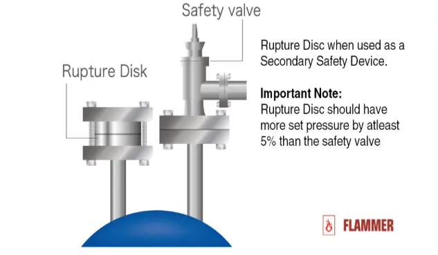
Rupture Disc and Safety Valve in Parallel
In these installations Rupture Discs are installed on a separate nozzle from that of the Safety Valve. The Safety Valve usually has a set pressure lower than that of the Rupture Disc by at-least 5%. During an overpressure event the relief valve will lift first and will start relieving the excess flow. If flow capacity of relief valve is sufficient it will reset at a pressure 3 to 10% lower than the safety valve set pressure (blowdown pressure). The reaction process will continue it’s operation.
If the flow relief capacity of safety valve is exceeded, pressure inside reactor will continue rising. Once it reaches the rupture disc burst pressure, the rupture disc bursts and relieves the pressure. Rupture Disc relieves the pressure till it reaches ambient atmospheric pressure condition. Thus causing overall shutdown of the process.
